

Disjuntores MT à Gás SF6 para Tensões até 40.5kV
Disjuntores MT à Gás SF6 para Tensões até 40.5kV

SF1 circuit breakers fixed version from 12 kV to 36 kV.

SF2 circuit breakers fixed version from 24 kV to 40.5 kV.

SF F400 circuit breakers withdrawable version from 24 kV to 40.5 kV.

General presentation
With over 37 years’ industrial experience in SF6 techniques and over 300,000 installed devices throughout the world, Schneider Electric is today one of the foremost manufacturers of SF6 switchgear. Schneider Electric has developed a wide range of high performance and reliable devices operating faultlessly on all 5 continents. Continuously increasing its performance, the company maintains a very high level of innovation in its offer.
The advantages of proven technology
Safety
The breaking medium is sulfur hexafluoride (SF6) used at low pressure.
The insulating enclosure containing the circuit breaker pole(s) is equipped with a safety membrane.
In addition, the rated characteristics, breaking the rated current under the rated voltage, are generally maintained at zero relative bars of SF6.
Reliability
The motor-charged spring stored energy operating mechanism is a key factor of device reliability: Schneider Electric cumulates 37 years’ experience with this type of mechanism, 300,000 of which are already in operation. Schneider Electric’s mastery of design and the testing of sealed systems guarantees sustained device performance for at least 30 years.
Increased endurance
The mechanical and electrical endurance of Schneider Electric SF6 breaking devices are in conformity with the most demanding specifications recommended by the IEC. These devices therefore meet requirements for even the most exposed of networks.
Less maintenance
Throughout the device’s service life, which in normal operating conditions may be at least 30 years, the only maintenance required is on the mechanical operating mechanism, once every 10 years or every 10,000 operations.
Although no maintenance is performed on poles, a diagnosis is possible:
» contact wear can be checked by external pole measurement.
» SF6 pressure can be continually monitored by a pressure switch.
Environmentally-friendly
Schneider Electric devices have been designed to ensure protection of the environment:
» the materials used, both insulating and conductive, are identified and easy to separate and recycle.
» the SF6 gas is under control from production through to the circuit breaker’s end of life. In particular it can be recovered at the end of the circuit breaker’s life and re-used after treatment in line with the new European directive.
» an end of life manual for the product details procedures for dismantling and recycling components.
Quality Assurance
During production, each circuit breaker undergoes systematic routine tests in order to check quality and conformity:
» pole sealing check.
» checking the correct mechanical operation of the device.
» plus its associated locking mechanisms.
» checking simultaneous closing of contacts.
» checking power frequency insulation level.
» checking main circuit resistance.
» checking auxiliary circuit insulation.
» checking auxiliary circuit electrical resistance.
» checking switching speeds.
» checking the switching cycle.
» measuring the switching times.
The results are recorded on the test certificate for each device which is initialed by the quality control department.
Certification
The quality system for the design and production of SF range circuit breakers is certified in conformity with ISO 9001: 2000 quality assurance standard requirements. The environmental management system adopted by Schneider Electric production sites for the production of SF range circuit breakers has been assessed and judged to be in conformity with requirements in standard ISO 14001.

Breaking principle
Breaking principle: puffer type
SF circuit breakers use the puffer principle with SF6 gas.
This methods cools and extinguishes the electrical arc as it passes through zero current by puffing a gas compressed by a piston attached to the moving contact. The gas is channeled by an insulating nozzle towards the tubular arcing contacts that are used as an exhaust.
This breaking technique is used for high-performance breaking applications (40.5 kV-31.5 kA) and has been used for the past 37 years.
The operating sequence in a puffer-type breaking chamber with the moving part actuated by a control mechanism is as follows:
 » the circuit breaker is closed.

» following an opening order the main contacts separate (a) and the current is directed into the breaking circuit (b). When the main contacts start
to open the piston (c) slightly compresses the SF6 gas in the compression chamber (d).

» an electrical arc appears on separation of the arcing contacts. The piston (c) continues its travel downwards. A small quantity of the gas channeled by the insulating nozzle (e) is injected towards the arc. For low current breaking, the arc is cooled by forced ventilation. However, for high currents the thermal expansion moves the hot gases towards cooler parts in the breaking unit. The distance between arcing contacts becomes sufficient to allow breaking of the current when it passes through zero due to the dielectric properties of the SF6 gas.

» the moving parts finish their movement and injection of cold gas continues until the contacts are fully open. The circuit breaker is open.
Panorama
SF range circuit breakers

Protection, monitoring and control

SF1 and SFset circuit breakers fixed version

Description of the device
The basic withdrawable version of the SF circuit breaker comprises:
» 3 main independent poles, that are mechanically linked and each comprising a “sealed pressure system” type insulating enclosure. The sealed enclosure is filled with low pressure SF6 gas.
» a stored energy operating mechanism of manual RI type (that can be electrically operated as an option).
This gives the device an opening and closing speed that is independent of the operator, for both electrical and manual orders.
When equipped with an electrical operating mechanism, the circuit breaker can be remotely controlled and it is possible to carry out reclosing cycles.
» a front panel housing the manual operating mechanism and status indicators.
» upstream and downstream terminals for the power circuit connection.
» a terminal block for connection of external auxiliary circuits.
According to its characteristics, the SF circuit breaker is available either in frontal version or in lateral version.
Each device can be optionally equipped with:
» an electrical operating mechanism.
» a support frame fitted with rollers and floor securing brackets for a fixed installation b locking of the circuit breaker in the open position by a keylock installed on the control panel.
» a pressure switch for the high performance versions.
» a Harting 42-pin type LV connector.
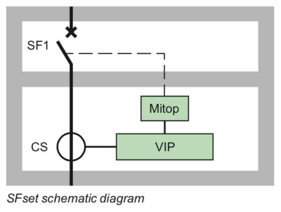
The SFset includes an independent protection chain
The SFset is provided with a fully autonomous integrated protection chain (with a VIP type control unit) operating without an auxiliary power source. The VIP protection unit exists in two models: VIP300P and VIP300LL.

Depending on the model, the unit provides protection against phase over-currents and earthing faults.
VIP protection units are associated with functional current sensors.
Two interchangeable sensors, CSa and CSb, are sufficient to cover all requirements from 10 to 1250 A.
SFset is delivered equipped and cabled with its protection chain, this simplifies panel builders’ installation work.
Applications
SF circuit breakers are 3-pole MV circuit breakers for indoor installation.
They are mainly used for switching and protection of networks from 12 to 36 kV in primary and secondary power distribution.
Because the SFset protection chain is autonomous in terms of power, this circuit breaker is particularly suited to certain dispersed installations on the network.
The autocompression breaking technique used in these circuit breakers means that making or breaking all types of compacitive or inductive currents can be achieved without dangerous overvoltages for the switchgear connected to the network.
The SF circuit breaker is therefore well suited to operating capacitor banks.
Electrical characteristics according to IEC 62271-100

Specific applications
Switching and protection of capacitor banks
SF range circuit breakers are particularly well suited to switching and protection of capacitor banks; they are classed C2 according to standard IEC 62271-100. Tests carried out according to the standard for breaking at 400 A with making and breaking cycles in case of a capacitor bank with a making current of 20 kA. Additional tests have been carried out: please consult us.

Description of functions
RI stored energy operating mechanism Wiring diagram

Manual or electrical operation of the RI stored energy operating mechanism
This gives the device an opening and closing speed that is independent of the operator whether the order is electrical or manual.
The electrical control mechanism carries out reclosing cycles and is automatically recharged by a geared motor each time after closing.
It consists of:
» the stored energy operating mechanism which stores in springs the energy required to open and close the device.
» a manual lever-operated spring arming device.
» a geared electrical arming device which automatically re-arms the control mechanism as soon as the circuit breaker is closed (optional).
» manual order devices by push buttons on the front panel of the device.
» an electrical remote closing device containing a release with an antipumping relay b an electrical opening order device comprising one or several release units which can be of the following type:
• shunt opening.
• undervoltage.
• Mitop, a low consumption release, used only with the Sepam 100 LA protection relay.
» an operation counter.
» an “open/closed” position indicator device with a mechanical indicator.
» a device for indicating “charged” operating mechanism status by mechanical indicator and electrical contact (optional).
» a module of 14 auxiliary contacts whose availability varies according to the diagram used.
Wiring diagram (principle)

Description of functions
Opening circuit
Composition
The opening circuit can be produced using the following components:
» a shunt opening release (on energizing) (YO1).
» a second shunt opening release (on energizing) (YO2).
» undervoltage release (YM).
» low energy release (Mitop).
Note: see the table of the releases’ combinations page “Order form” .

Shunt opening release (YO1 and YO2)
Energizing this unit causes instant opening of the circuit breaker.

Undervoltage release (YM)
This release unit causes the systematic opening of the circuit breaker when its supply voltage drops below a value less than 35% of the rated voltage, even if this drop is slow and gradual. It can open the circuit breaker between 35% and 70% of
its rated voltage. If the release unit is not supplied power, manual or electrical closing of the circuit breaker is impossible. Closing of the circuit breaker is compulsory when the supply voltage of the release unit reaches 85% of its rated voltage.

Low energy release (Mitop)
This specific release unit comprises a low consumption unit and is specifically used for Sepam 100LA self-powered relays.

Description of functions
Remote control
Function
Remote control enables the remote opening and closing of the circuit breaker.
Composition
The remote control mechanism comprises:
» an electrical motor with gearing.
» a shunt closing release (YF) combined with an anti-pumping device.
» an operation counter.
Electrical motor with gearing (M)
The electrical motor carries out the automatic rearming of the stored energy unit as soon as the circuit breaker is closed. This allows the instant reclosing of the device after opening. The arming lever is only used as a backup operating mechanism in the case of the absence of the auxiliary power supply.
The M3 contact indicates the end of arming operations.

Shunt closing release (YF)
This release allows the remote closing of the circuit breaker when the operating mechanism is armed.
Operation counter
The operation counter is visible on the front panel.
It displays the number of switching cycles (CO) that the device has carried out.
Description of functions
Indication and locking/interlocking

“Open/closed” auxiliary contacts
The number of contacts available depends on the options chosen on the operating mechanism.
In the basic configuration, the circuit breaker’s operating mechanism comprises
a total of:
» 5 normally closed contacts (NC).
» 5 normally open contacts (NO).
» 1 changeover contact (CHG).
The usage procedure for auxiliary contacts is given in the following table:

In order to know the final number of available contacts, you must deduct the total number of contacts included in the circuit breaker (5 NC + 5 NO + 1 CHG), the number of contacts used given in the table above.
E.g.: a circuit breaker equipped with a remote control and a shunt trip unit has the following available contacts:
5NC+4NO+1CHG.
With a undervoltage release instead of the shunt trip, this circuit breaker would have the following available contacts:
5NC+5NO+1CHG.

Locking the circuit breaker in the “open” position
This key-operated device allows the circuit breaker to be locked in the “open” position. The circuit breaker is locked in the open position by blocking the opening push button in the “engaged” position.
Locking is achieved using a Profalux or Ronis captive key type keylock.
Protection, monitoring and control
VIP300 protection unit

The SFset circuit breaker has an integrated and independent protection system
The SFset circuit breaker comprises an SF1 into which is integrated a protection system comprising:
» a set of current sensors installed on the lower current terminals of the pole units. Two interchangeable sensors, CSa and CSb, sufficient to cover all requirements from10Ato1250A.
» a VIP type protection relay mounted on the control unit.
» a “Mitop” low consumption, release unit installed on the switching device. The unit is fully independent and functions without an auxiliary power supply.
Operating principle
The protection system is supplied power by sensors which supply:
» the “current” information, processed by the protection unit
» the electrical power required for the whole protection system to operate ; VIP unit and Mitop release.
All settings are visible and accessible from the front of the device.
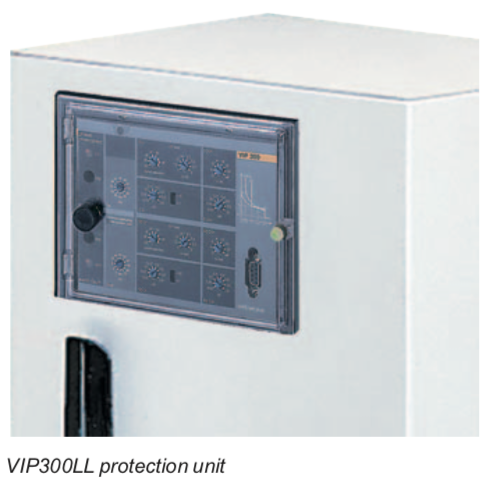
VIP300P and VIP300LL independent protection unit
The VIP300 unit is intended to be installed on distribution networks. It can be used to protect an MV/LV transformer, to protect the head of an industrial installation, but also to protect a branch.
The VIP300 provides protection against phase-to-phase faults and against earthing faults. The choice of trip curves and the large number of settings enable it to be used in a large number of discrimination arrangements.
The VIP300 is an independent unit supplied power from the current sensors; it does not require an auxiliary power supply. It activates a Mitop release unit. The VIP300 exists in 2 models:
» VIP300P:phaseprotection
» VIP300LL:phaseandearthingprotection.

Phase protection (VIP300P, VIP300LL)
Phase protection has two independently adjustable thresholds:
» the lower threshold can be chosen to be either definite time or inverse definite time. It can be executed according to the RI curve.
» the upper threshold is inverse definite time.
The definite time curves are in conformity with standard IEC 60255-3.
They are either of type inverse (SI), very inverse (VI) and extremely inverse (EI).
Earthing protection (VIP300LL)
Earthing full protection functions with the measurement of residual current: this is carried out based on the sum of secondary currents in the sensors.
As for phase protection, earthing protection has two independently adjustable thresholds.
Indication
Two indicators show the origin of the release (phase or earth).
They stay in position after breaking the release unit power supply.
Two LED indicator lights (phase and earth) show that the lower threshold has been exceeded and that the time delay has been started.
Protection, monitoring and control
Trip curves
VIP300P and VIP300LL

Definite time curves

Protection, monitoring and control
Current sensors and test unit for VIP300

CSa and CSb current sensors for the VIP300
In order to achieve the specified performance levels, the VIP300 protection unit must be used with the specified sensors. The combination of the unit/sensor
is essential in order to comply with characteristics and in particular with:
» operation throughout the whole range
» response time
» accuracy
» short circuit thermal withstand.
Two interchangeable sensors, CSa and CSb, suffice to cover all requirements from10Ato1250A.

VAP6 test unit
VIP type protection units have a “test”, socket to connect a VAP6 test unit. This portable unit with its own power supply enables the correct functioning of the protection unit to be checked.
Dimensions
Basic fixed unit

Fixed unit with support frame

Connection

